For a ZIP File with this information in Real-Text Format and Text Format with all diagrams, click here.
PROJECT THROTTLE BODY
BY
DANIEL SPRAGUE (DESST33@PITT.EDU)
PLEASE READ: The modification listed below is not for the faint of heart, the litigious, or the mechanically disinclined. There is a good chance that you can DESTROY your throttle body or engine if you do not use common sense/mechanical skill. This is provided strictly for INFORMATIONAL purposes only and I will not be responsible for anything you do or not do. It has been several years since I did this; therefore this text may be incomplete. Remember that the throttle body is expensive and the engine much more so. Also any modification may not be legal for use on pollution controlled/street driven vehicles. Performance is not guaranteed should you choose to do anything with this info. Also remember this is NOT something that can be done in a few short hours -- expect to be without your car for two weeks at least.
IF YOU HAVE ANY DOUBTS ABOUT THIS OR DISAGREE WITH ANY OF THE ABOVE, STOP RIGHT HERE. Your motor is much happier now than if it swallowed a throttle plate!
Also READ EVERYTHING BEFORE YOU BEGIN, so you know what you are getting into and to be sure you have the skills needed to finish!
That aside, this is a fairly simple, but time consuming modification. It applies specifically to the 48mm throttle body as used on the 85-92 GM Tuned Port Injection, but the general procedure is applicable to most fuel injected engines (including TBI) with slight modification. This is also an effective mod, even on mild motors. According to Engines magazine (1992, pg 126) this modification "significantly improved power without changes to the computer or exhaust system ... The car's (1985 IROC) horsepower was improved throughout the power range, giving it better drivability in traffic and a large horsepower boost in the high-RPM range. ... On the dyno, rear horsepower increased significantly in the 4500 range, from 145 to 160." (A chip was also used for the dyno test.) The reason that this is such an effective mod is that more air can flow at any given throttle angle; I do not know how much it increased my WOT performance, but it felt crisper and more responsive all around after performing this modification; I highly recommend it. It took me around 10 hours or so to do all the work needed; I spread it out over about two weeks. Keep in mind that even if you rush it you must still allow a time for the epoxy to dry. (see below)
Here's what you'll need:
Brake cylinder hone
Set of full size (engine cylinder) stones
Drill
Aluminum sheet for throttle plates (see text)
Throttle body gasket set (about $15 from GM)
Cold weld epoxy (Loctite Wield or eq.)
Dremel tool
Screws, bolts as needed (see text)
Small tube (see text)
WD-40 or eq.
Accurate ruler or micrometer
Blue (or red) Loctite
The usual toolbox stuff
Here's what to do:
STEP 1 -- Taking it apart.
Remove the throttle body. Remove the IAC and TPS. Remove the top and bottom plates. Some of the screws on the bottom of mine were frozen and broke off when I tried to loosen them. After getting the others out though, the piece came off with a little prying. (be sure not to distort the surface though!) The broken screws then came out easily with vicegrips. Next, use the Dremel tool to remove the flash coating that holds the throttle plate screws in. Be aware that this is some kind of titanium/depleted uranium invincimetal! After getting the screws out remove the throttle plates and the retaining clip that holds the shaft in on the TPS side. This clip is press fitted, so prying/some grinding of the shaft is required. Pull the throttle shaft out and finish removing any broken screws/ flash coating--this stuff ate 2 titanium drill bits before I finally pounded it out with a hammer and nail!
STEP 2 -- Epoxy the EGR area. (see figure 1 - click on diagram for enlargement)
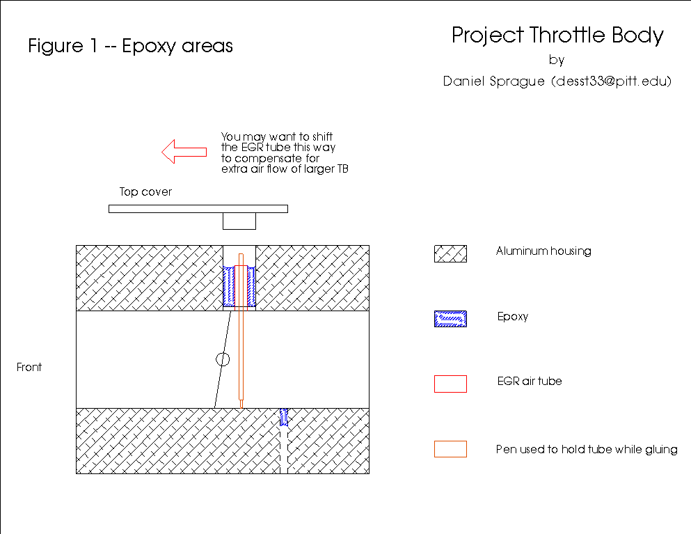 The
stock casting is very thin above the EGR hole, and needs to be epoxied
to go past 50 mm or so. There is also a screw hole in the bottom which
will be cut into by the honing process and needs treated. I started by
cleaning the EGR well area up using carb cleaner and sandpaper. This is
a tight area right above the square hole behind the throttle plates. Be
sure to prepare well, so that the engine does not eat your epoxy job! After
getting it prepped for the epoxy, acquire a tube about the same diameter
as the square hole on bottom; 1/8" or so. I used a piece of broken
antenna, but you can get brass tube at a hobby shop. Cut this tube to fit
as shown in the diagram, then install it. Don't forget that there is a
dip in the top cover, so be sure that the tube clears this. The tube may
be held in place using the ink cartridge of a ball point pen. Try to keep
the tube as far forward as possible to account for the additional airflow
of the bored throttle body. (I've had an EGR code set on one or two occasions
since I didn't do this.) Mix up the epoxy. Be sure it is fresh and flows
easily. Epoxy the sucker in as per the diagram. Don't worry about the screwhole
your going to bore into at this time, though. Allow plenty of time to dry.
The
stock casting is very thin above the EGR hole, and needs to be epoxied
to go past 50 mm or so. There is also a screw hole in the bottom which
will be cut into by the honing process and needs treated. I started by
cleaning the EGR well area up using carb cleaner and sandpaper. This is
a tight area right above the square hole behind the throttle plates. Be
sure to prepare well, so that the engine does not eat your epoxy job! After
getting it prepped for the epoxy, acquire a tube about the same diameter
as the square hole on bottom; 1/8" or so. I used a piece of broken
antenna, but you can get brass tube at a hobby shop. Cut this tube to fit
as shown in the diagram, then install it. Don't forget that there is a
dip in the top cover, so be sure that the tube clears this. The tube may
be held in place using the ink cartridge of a ball point pen. Try to keep
the tube as far forward as possible to account for the additional airflow
of the bored throttle body. (I've had an EGR code set on one or two occasions
since I didn't do this.) Mix up the epoxy. Be sure it is fresh and flows
easily. Epoxy the sucker in as per the diagram. Don't worry about the screwhole
your going to bore into at this time, though. Allow plenty of time to dry.
STEP 3 -- Bore! (And bore, and bore, and bore)
This is the time consuming part. Install the larger stones onto the brake hone. These are used in order to cut time and produce a more even job. Start boring the throttle bodies using the brake hone. Be sure to keep the hone moving up and down in order to bore evenly. Spray the WD-40 on the hone stones/cylinder as you bore to clean and lubricate the area. Periodically remove the hone to wipe out the area and measure your progress. After a few hours you will bore through the screw hole on the bottom. As soon as this happens, get the throttle body clean and WD-40 free, mount the bottom cover and screw a screw into the offending hole. Be sure to put a dab of grease on the screw so that it is not epoxied in. Epoxy the hole where you bored into it, wiping off any excess. Do not worry if the job is not perfect as the area will clean up as you continue boreing. After the epoxy dries thoroughly, continue to bore. It took me several hours of boring to open both up. I got tired and stopped at 51.5 mm, but you should be able to go to 52 mm (It looks awful thin, though!) For ultimate performance, radius the lips with fine sandpaper when finished.
STEP 4 -- Prep the throttle shaft.
If you messed up the screw holes as I did, get some brass screws in the next larger diameter at the hardware store, and a tap. Tap out the holes. Straighten if bent. That's it!
STEP 5 -- Make the throttle plates (see figure 2 - click on diagram for enlargement)
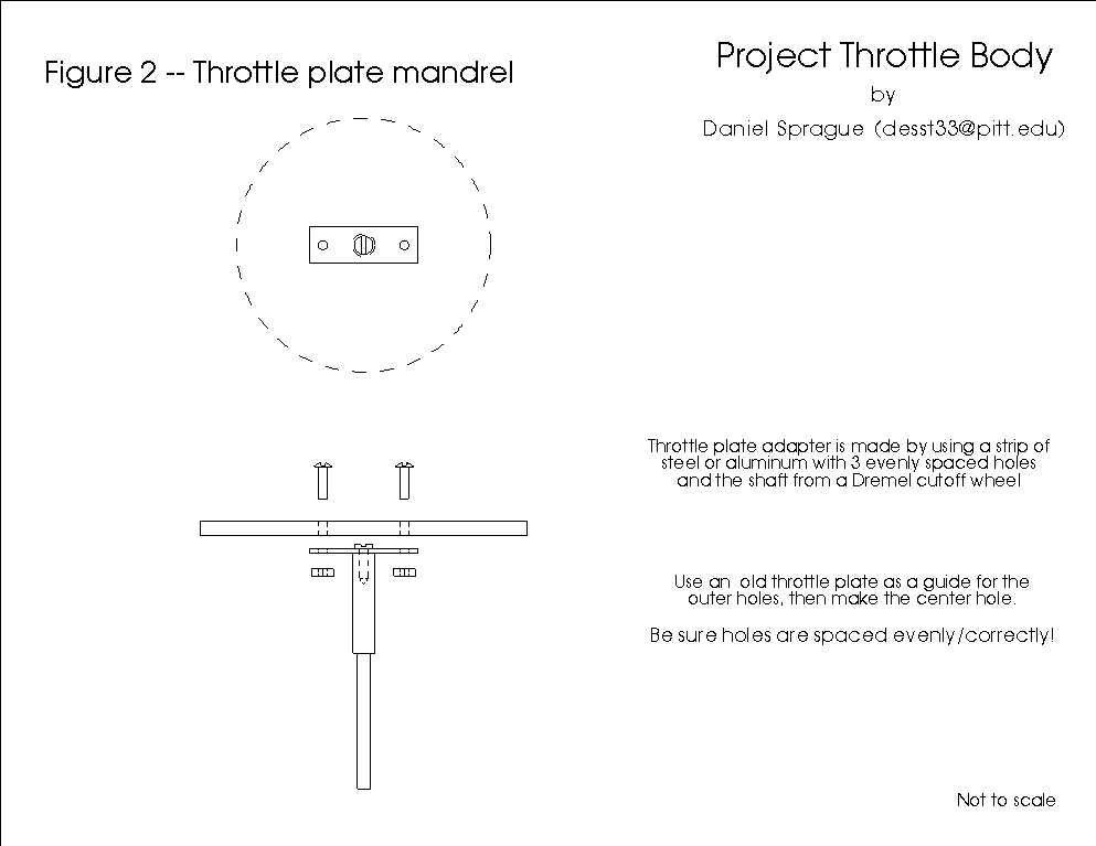 Here
you need to be choosy about the aluminum you use. You want something thin
for better airflow, but not too thin that engine vacuum destroys it. I
cut what I needed from an old computer power supply. It is about 2/3 as
thick as stock and works well. Start by cutting it to roughly the size
you need. Using the stock throttle plates as a guide, drill holes in the
new throttle plate and the mandrel you'll make. Mount the mandrel on the
Dremel tool or drill, and hold the throttle plates against sandpaper or
a grinding wheel. Grind until the plate is balanced (e.g. round) and about
the correct size as measured with the ruler. Use fine sandpaper to clean
up any sharp edges and test fit. You will know the size is right when it
fits the throttle body like the stock plates did (just wide enough to fit
and at a 5 to 10 degree angle).
Here
you need to be choosy about the aluminum you use. You want something thin
for better airflow, but not too thin that engine vacuum destroys it. I
cut what I needed from an old computer power supply. It is about 2/3 as
thick as stock and works well. Start by cutting it to roughly the size
you need. Using the stock throttle plates as a guide, drill holes in the
new throttle plate and the mandrel you'll make. Mount the mandrel on the
Dremel tool or drill, and hold the throttle plates against sandpaper or
a grinding wheel. Grind until the plate is balanced (e.g. round) and about
the correct size as measured with the ruler. Use fine sandpaper to clean
up any sharp edges and test fit. You will know the size is right when it
fits the throttle body like the stock plates did (just wide enough to fit
and at a 5 to 10 degree angle).
STEP 6 -- Putting it all together
Install the throttle shaft and plates. Check for binding in the throttle plates which indicates they are too large. Do not expect the plate to seal perfectly, there may be small gaps here and there. Just be sure there aren't any large gaps when the throttle is shut or your engine won't idle! If it looks good, Loctite the plate screws in. Install the retaining clip on the end of the shaft and stake in place with a hammer & screwdriver. Bolt everything else up, (you may want to Locktite the screws so they don't rust in and break (again!)) and your ready to go. Ideally you will be able to set the idle at 400-450 stock, but mine leaked some at first and my idle was about 1000. Inevitably the throttle plates will wear in and you will be able to set factory idle, though.
Reliability: Hopefully if you do everything right the unit will prove as reliable as stock. I did mine back in 93 or 94 and have had no trouble with it. (except the EGR problem as listed above) My fears of the screws/epoxy being swallowed by the engine have (so far) been found to be needless. That's about all there is to it, go and enjoy the extra performance of your new throttle body!
Feel free to mail any questions, comments, statements suggestions, or problems to the address at top. Also let me know if you found this info to be useful, as I have several more homegrown mods that I could write up, but don't complain to me if you have chosen to disregard the warning on the first page and blow your motor up!