Category Archives: Technology Insights
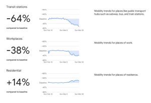
Google’s Role in Social Distancing
The more you know!
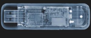
Believe it or not, they get lighter. USB drives use Flash memory, which means the the ones and zeros of your data are stored on transistors. When you save data, a binary zero is set by charging the float gate of the transistor, and a binary one is set by removing the charge. To charge it, we add electrons, and the mass of each electron is 0.00000000000000000000000000091 grams. This means that an empty USB drive (which mostly holds zeros) weighs more than a full USB drive (which has ones and zeros). Add data, reduce the weight. However, you would need to weigh more USB drives than exist on the planet together at once before the difference in weight became easily measurable.
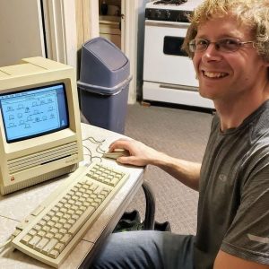
No, it’s not 1987, it’s 2019… (An Apple IIgs prints a “Print Shop” sign in 2019)
The sights and sounds of antique technology. I bought a new ribbon off of Amazon to see if that’s the only thing that was needed to bring this old ImageWriter II to life.
This is a fully operational Apple IIgs with a 5 1/4″ and 3 1/2″ floppy disk drive, color monitor, and ImageWriter II printer. The software running is “The Print Shop” by Broderbund.
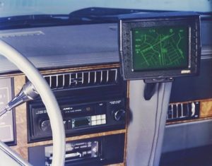
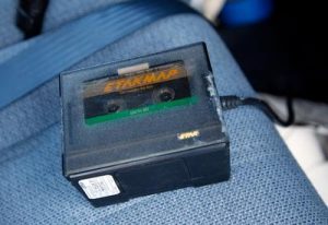
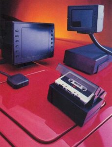
Computerized Car Navigation in 1986
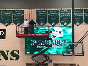
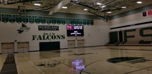
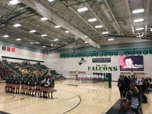
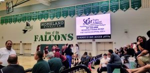
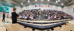
High-Resolution LED Display Graphics
Since the time these high-resolution LED displays were installed in the Nomeland Gymnasium at the High School, I’ve been spending much of my spare time designing graphics, sponsor advertising, and program workflow for the system. It has already been used successfully for several volleyball matches, 9th grade orientation, and now an all-staff District workshop. The variety of technology I get to work with is one reason I love my job and this field!
Like it or not, electric cars are the future.
Anybody in their 30s or 40s now will definitely be living in a world where electric cars, charged by renewable energy such as solar or wind power, will be the majority of vehicles on the road. Major trucking companies have already put orders in for the Tesla Semi based on ROI for delivery in 2019. AND, they release an electric car that does an 8.9 second 1/4 mile with a 600 mile range at highway speeds.Gasoline and diesel engines will go the way of the steam engine in the next 30-40 years.
Digital Video Editor Certification is now Available!
Facebook’s Artificial Intelligence and ALT Tags
The last T1 has been disconnected!
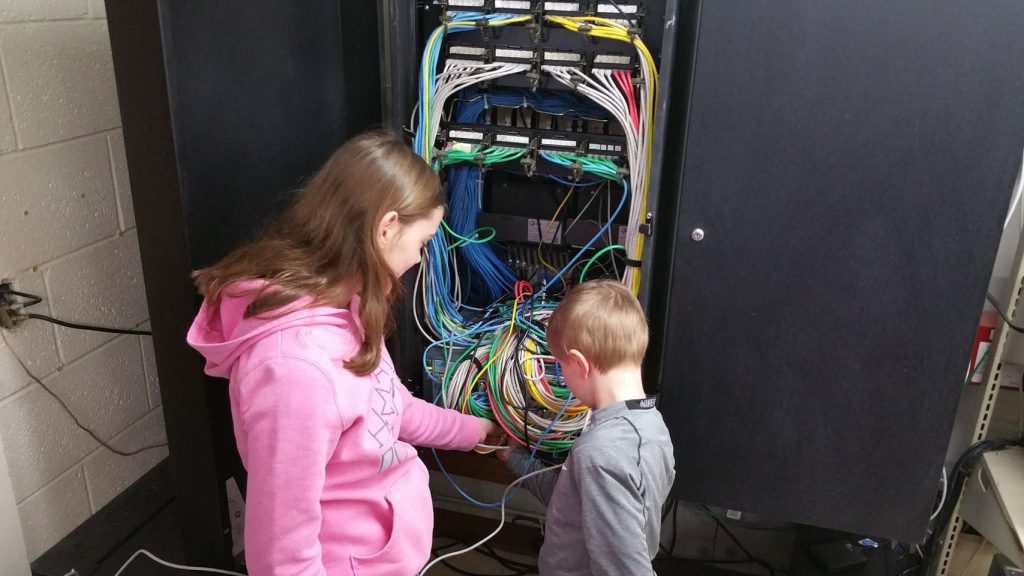
Once the configuration was done, the only thing left to do was plug in the fiber! As you can see, a few Nerstrand Elementary School students happily helped out with this process. With a simple, positive “click” of the fiber-optic patch cable into the transceiver, Nerstrand completed their upgrade from the two trunked T-1 lines offering about 3Mbps of bandwidth, to the 10000Mbps of bandwidth now at their disposal. The speed is exciting, but even more exciting is the capacity this line will give the School for bringing in more devices and perhaps even having a one device per student option down the road. Thanks Amelia and Stefan!
Stealing 3D Models by Audio Recording a 3D Printer
A bright professor at the University of California-Irvine discovered it’s possible to steal the design of a 3D model by simply doing an audio recording of the 3D printer printing it. Apparently, they have demonstrated a 90% accuracy of model reconstruction using this technique. Simply having an employee working at a manufacturing facility with a cell phone on them could invite the possibility of industrial espionage if they were to give such a recording to a competitor. Fascinating proof of concept!
1992 SouthLAN/MNWADA Joint Packet Radio Node Install at Faribault
During much of 1991, the SouthLAN and MNWADA Packet Radio Clubs in Southern Minnesota planned and designed 3 high-speed packet radio nodes to be installed at Apple Valley, Faribault, and Dodge Center. The Faribault site, MNFBL:N0QVC-1, would have a 1200 baud user frequency on 145.01 MHz, a 9600 baud backbone towards Dodge Center on 430.95 MHz, and a 19.2 kilobaud backbone towards N0DAI-1 in Apple Valley on 430.55 MHz.
This was one of the first high-speed amateur wireless data communications services in the upper midwest, and passed hundreds of messages between the Twin Cities Metro area and Rochester, MN throughout the 90s and early 2000s. All locations used WA8BXN’s MSYS bulletin board system and G8BPQ nodes, with a combination of Kantronics Data Engines and D4-10 radios. The N0QVC-1 Johnson RSDL VHF radio is still used as an APRS node on 144.39 in the Faribault area at this location as of 2016.
The video is a glimpse of the antenna and TNC install at the Faribault location on May 23, 1992.
A Good Knight to Use the 3D Printer
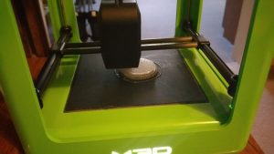
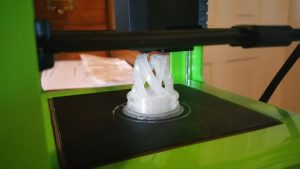
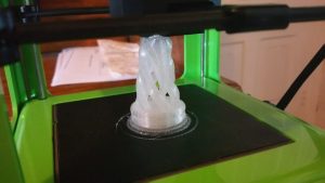
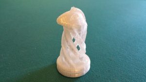
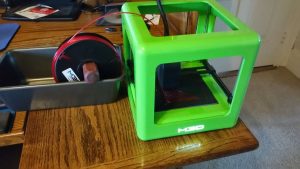
A spiral-inspired knight, today’s 3D printing project with my #M3D. Turned out great!
#Genius
Arthur C. Clarke in 1974, looking into the crystal ball on what life might be like with #computers in 2001. Pure #genius!
https://www.facebook.com/CosmosMagazine/videos/455483054467788
MisterHouse control for a Samsung Smart TV
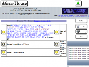 Another piece of my home, now automated. With assistance from a thread on the Samygo forum, I created a module for the MisterHouse Home Automation System which allows it to control a network-connected Samsung Smart TV. For instance, when you leave the house for more than 10 minutes, it could turn the TV off for you. It could also switch the TV automatically to match your favorite show schedule, or switch to an HDMI input to monitor a surveillance camera if motion is detected on your property. It’s available right here for free: https://gist.github.com/hollie/ed1fa39871e93e36e24e. It’s written in Perl so it’s cross-platform or can be adapted for other uses.
I’ve tested this with my Samsung UN40EH5300 and it works well. It should work on pretty much any Samsung TV that has an open port 55000. The code is based off of another Perl/HTML program from http://forum.samygo.tv/viewtopic.php?f=12&t=1792 created from some Wireshark traces.
To use this code, you’ll have to modify a few things:
– Change the IP 192.168.2.155 below to your own TV’s IP Address.
– Change $myip to your MisterHouse server’s IP Address.
– Change $mymac to your MisterHouse server’s MAC Address.

